Click to jump to latest post
FR-S / BRZ / GT86 Intake Manifold Progress
Scroll down for pictures
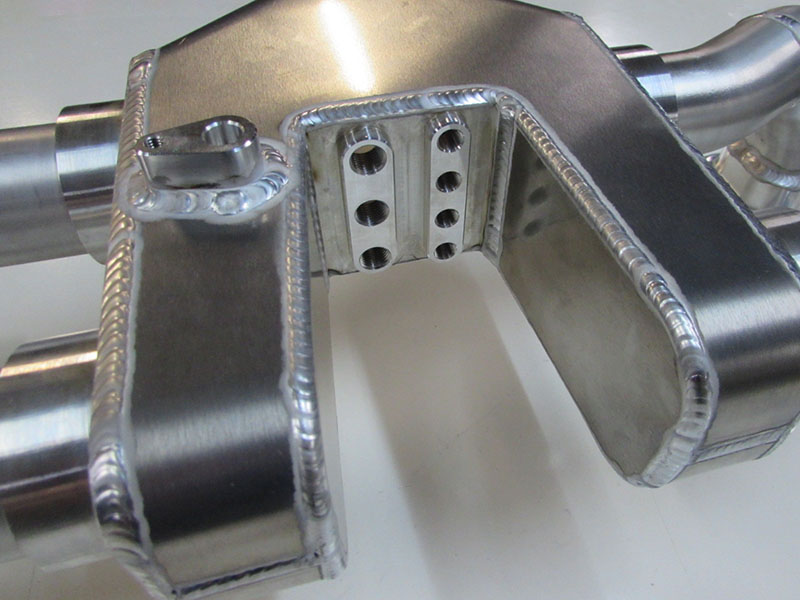
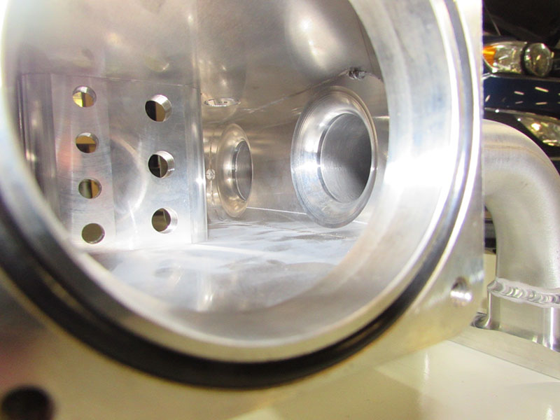
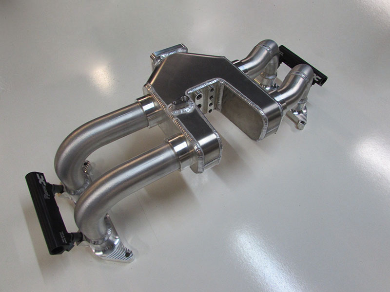
Why build an intake manifold? What we have found from our CFD models is that the OEM manifold air flow is considerably bias to the rear cylinders of the plenum. The manifold design below is our current and best iteration for even air flow to all cylinders. We accomplished this task by moving the back of the plenum wall forward, giving the manifold a “U-shape”. After multiple iterations of CFD analysis and moving the back wall forward, we found what was the best fit. The current manifold build represents this and hopefully performs reasonably better than the OEM intake manifold.
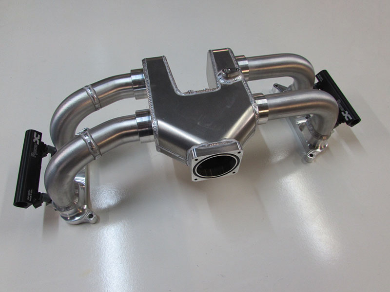
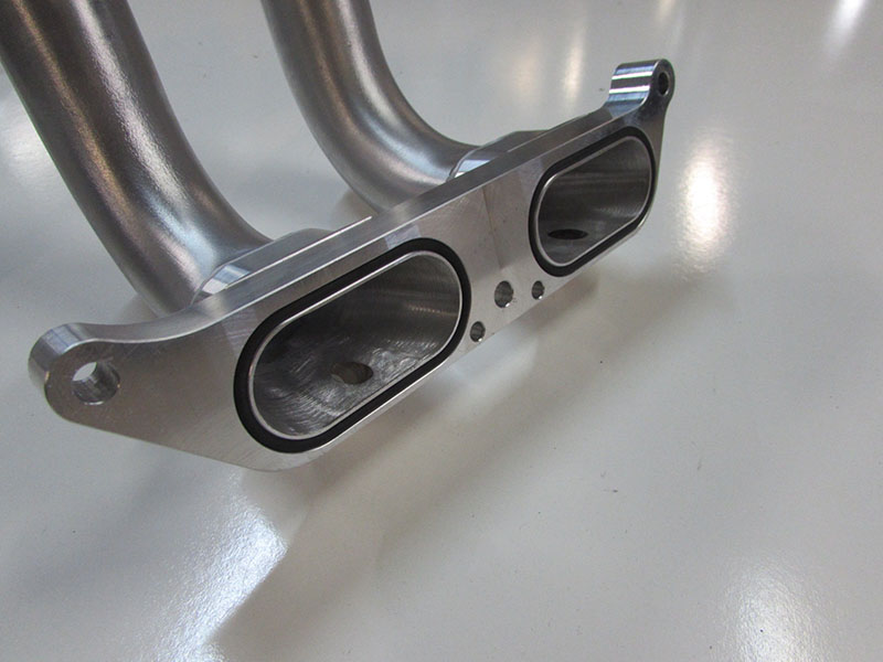
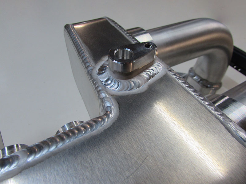
Besides the shape are there any other major changes? Yes, the manifold is about 1.5 inches taller than the OEM intake manifold and we have moved the throttle body forward about 2 inches. We made these changes to provide better air flow to all cylinders and hopefully gain the benefits of longer runners, much like the aluminum billet spacers for the OEM manifold. We have also added several NPT ports on the back of the manifold for easy vacuum reference.
If the intake manifold performs well, we will be releasing it for sale. The production version of the manifold would use mandrel bent runners and would eliminate the weld found on the right hand side of the manifold runners. The manifold will require tuning and we do not suggest using it on the OEM tune. We are seeing noticeable air flow differences from 3000 to 5000 RPM, enough so that its requiring additional fuel. Hopefully this will be another addition and step forward to further eliminating the torque dip commonly found with the platform.
If you have any questions, concerns or comments please let us know. We look forward to hearing from you.
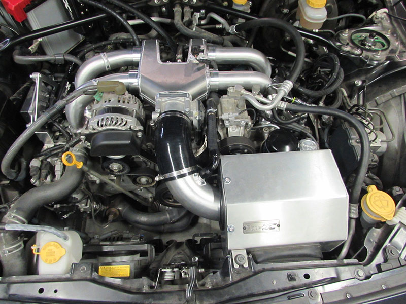
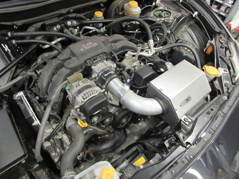 OEM intake manifold pictured above.
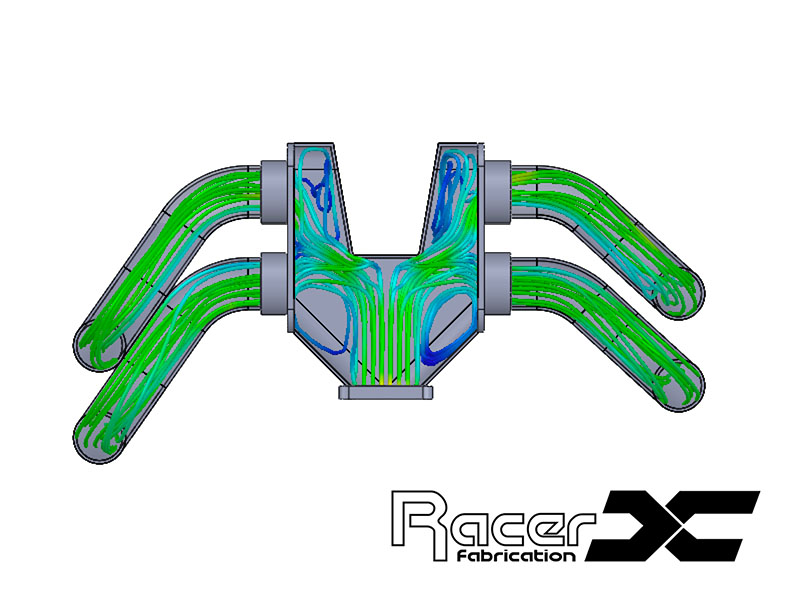 CFD for Racer X intake manifold above.
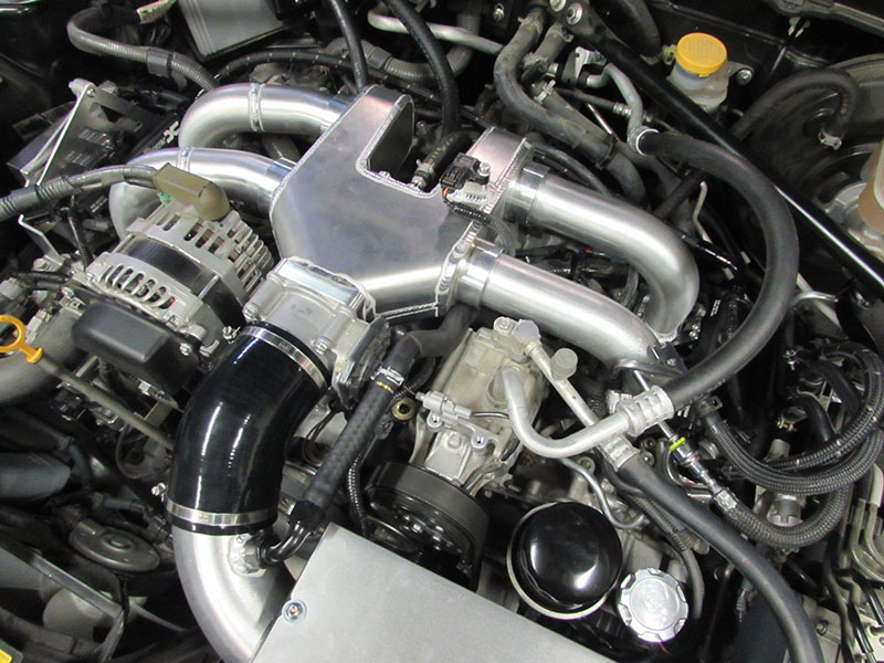
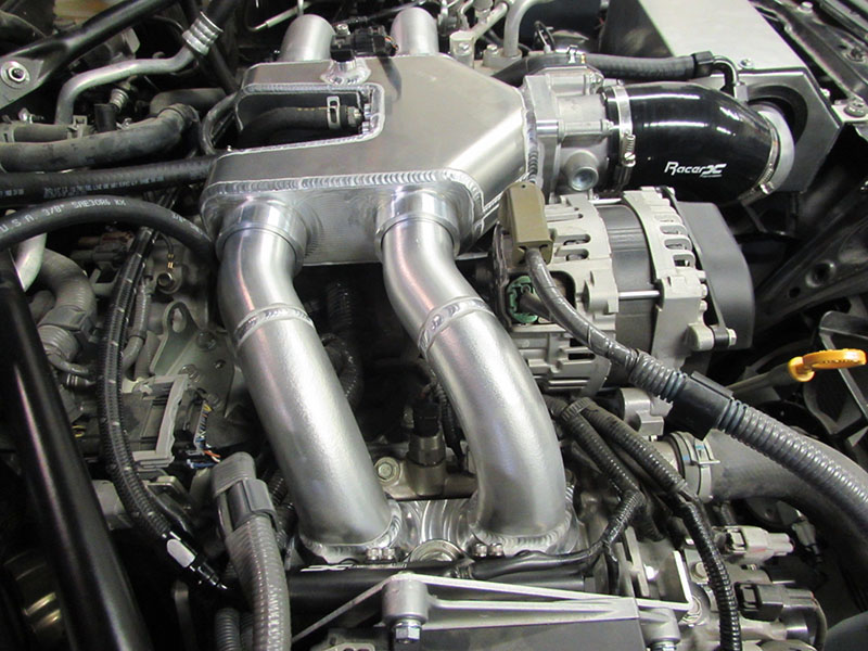
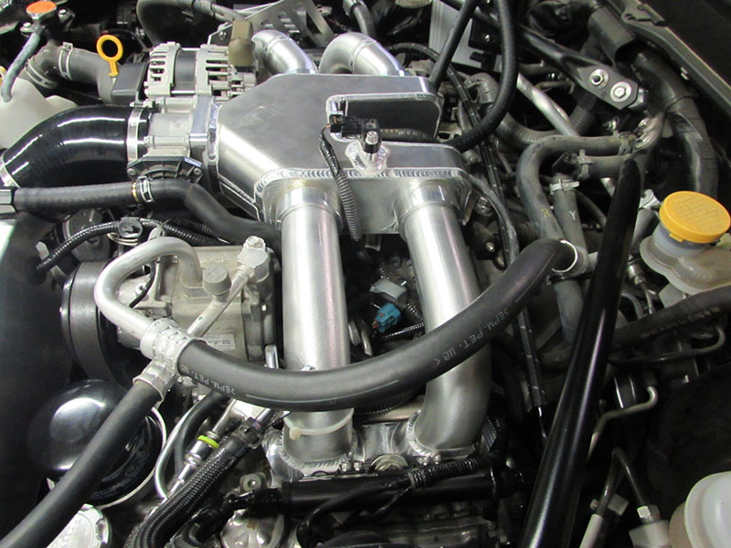
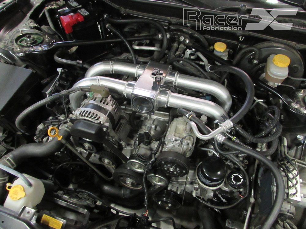
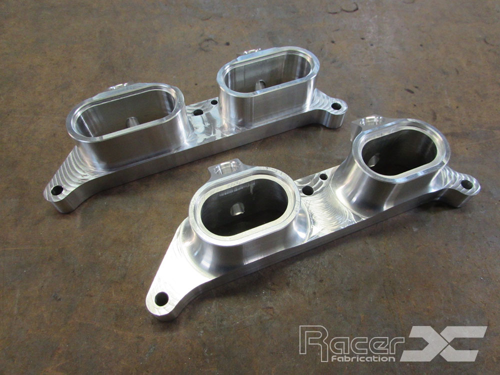
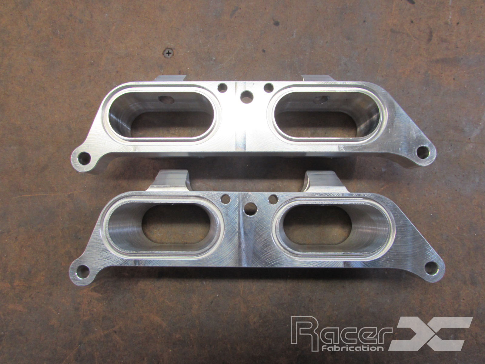
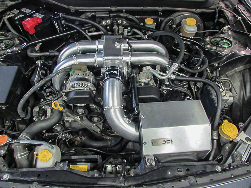
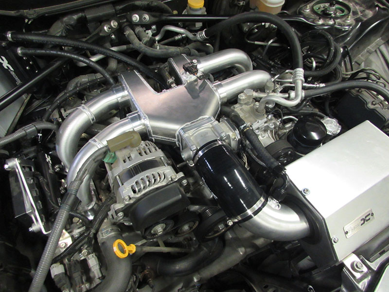 Racer X intake manifold installed. More detailed photos below.
Design, development and results
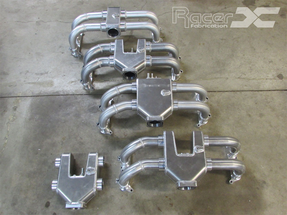
As some of you know, we have been tinkering with the intake manifold for a little over a year now, with the most work being completed in the last couple of months. We have openly stated that we have tested 4 intake manifold variations, but we have actually tested 6 and we still plan to test 2 more variations. Let’s start at the beginning and we can bring this to our current stage of development.
Design
The plenum, runner diameter, and runner length were the primary concern. We started with a plenum size that was slightly larger than engine displacement and quickly found that airflow was bias to the rear cylinders which is not of much surprise. If you look at the OEM manifold, it’s quite simple to see that would be the case. The runners closest to the throttle body make it difficult for air to enter. With our plenum design we moved the rear middle section of the plenum forward, ran several CFD variations to find a happy medium of airflow to all cylinders and then altered the radius and angle to optimize further. This worked quite well and would prove out in testing (or so we thought).
Next, we looked at runner diameter. We started with the intake valve diameter and multiplied this by 80%, all the way up to 120% (and slightly larger). We then used the closest runner diameters from standard material stock to find which diameter would provide the best velocity without hurting overall flow and in turn make best power. (We started with roughly 80% due to the fact that airflow passing the valve is not 100% efficient).
Finally, we moved on to runner length, although this is slightly more difficult due to the fact that it must fit in the engine bay and be packaged with the plenum and flanges. The runner length would remain unchanged with the exception of manifold #6 which would require a runner length that was roughly 1.5” longer.

Development
We started with the optimized plenum design for manifold #1. We used the smallest runner diameter and the standard runner length that would be used through out all of the testing. Manifold #1 would provide decent results at the beginning of the power band, but falls on its face around 5800 RPM. Our initial thought was the runner diameter is too small.
 Click graph to enlarge.
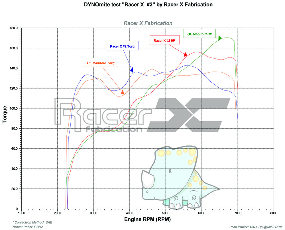
Manifold #2 would increase runner diameter by 7% (I know doesn’t seem like any change would happen). We found similar results, gains through the majority of the RPM range, but again falling around 5800 RPM but making more power than manifold #1 (around 10 whp). With this increase in power we decided to go back to manifold #1 and check to see if there was any power gain from increase plenum size.
 Click graph to enlarge.
Manifold #3 would increase the plenum size by 50%, the easiest increase would force us to comprise our optimized design. It would allow us to see if there were any differences or gains from increasing the plenum volume. The results would be quite similar to manifold #1, however there were slight losses in the bottom compared to manifold #1, but it would produce slightly more power at the higher end of the RPM range.
 Click graph to enlarge.
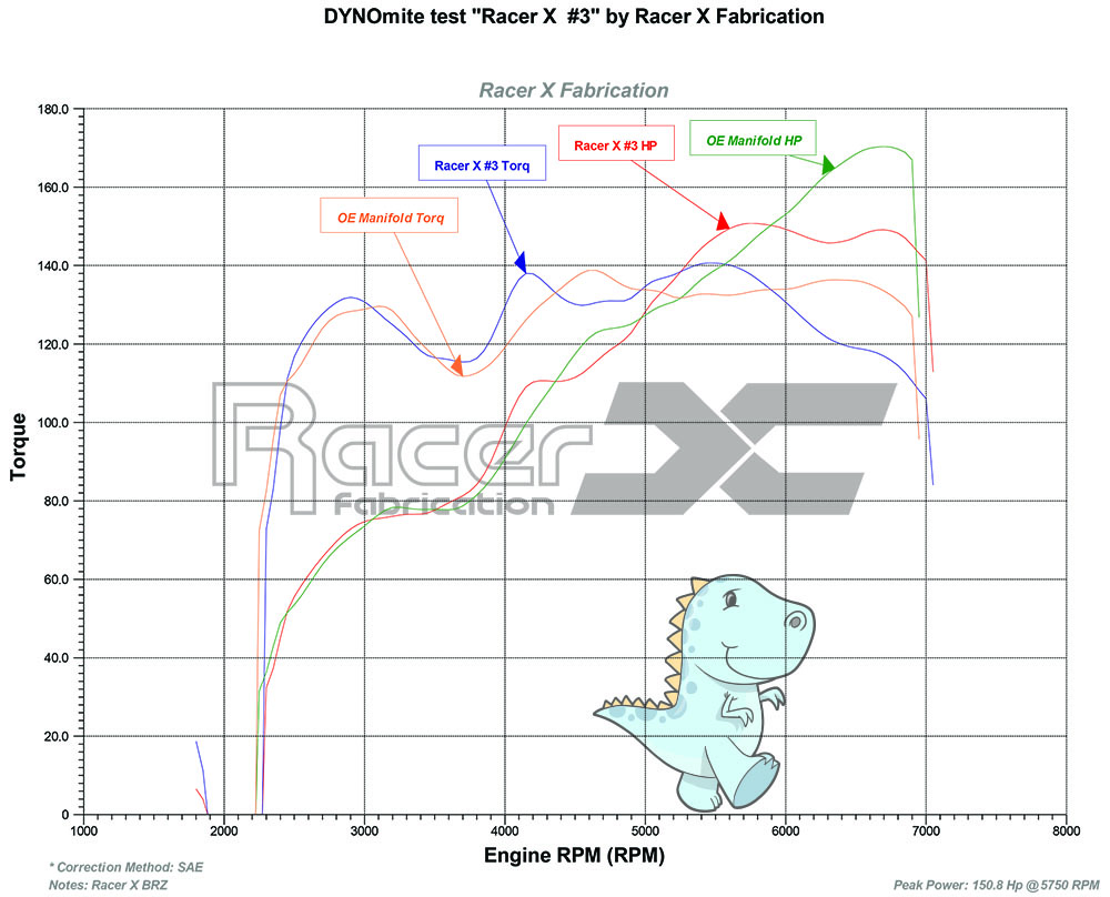
We concluded from the 3 previous tests that we would keep the optimized plenum design for manifold #4 and increase the runner diameter again. The runner diameter increase would be 21% this time. We thought this would yield much better power at the higher end of the RPM range, but after testing the results did not provide much, if any gain over manifold #2. This an anomaly to us, why did manifold #4 produce such similar results to #2? The conclusion was quite simple and we ended up redesigning our cylinder head flanges to accommodate the reasoning.
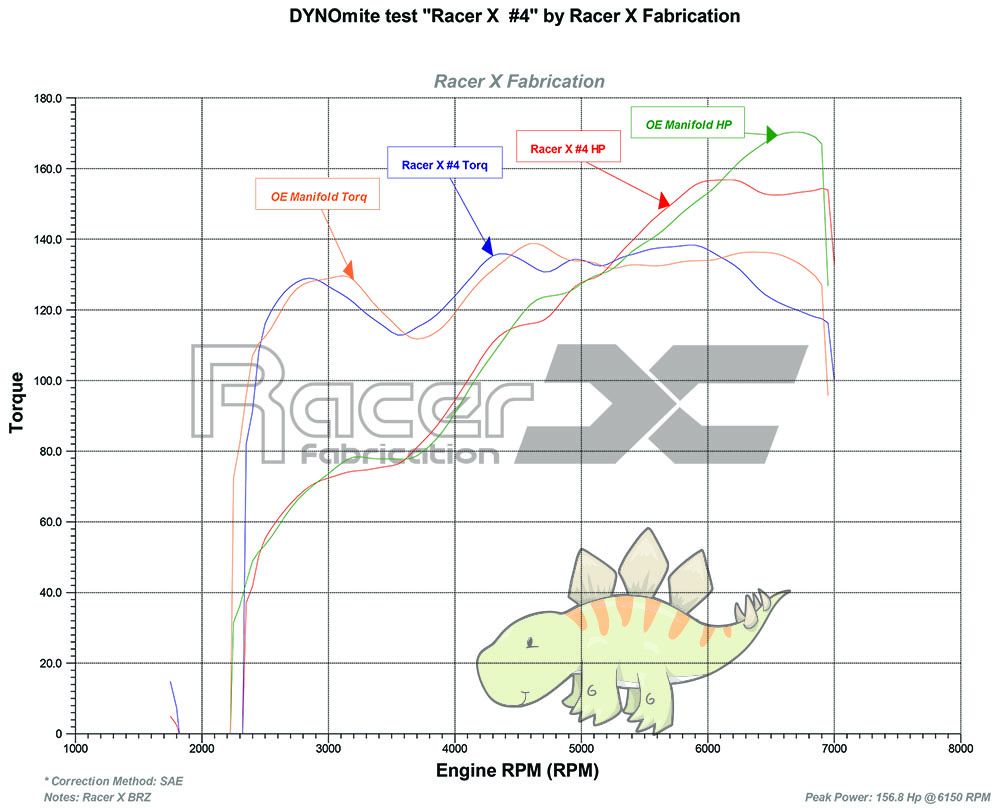 Click graph to enlarge.
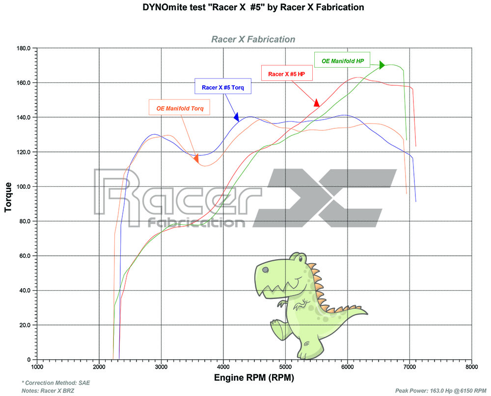
Manifold #5 was the same runner diameter, runner length and plenum, the only change would be the cylinder head flange. We determined the angle we used to open the flange was causing the airflow to decelerate enough that it was impacting overall power. Manifold #5 is currently the closest to overall power compared to the OEM manifold, with the exception of the low and mid RPM gains that can be seen in the graphs.
 Click graph to enlarge.
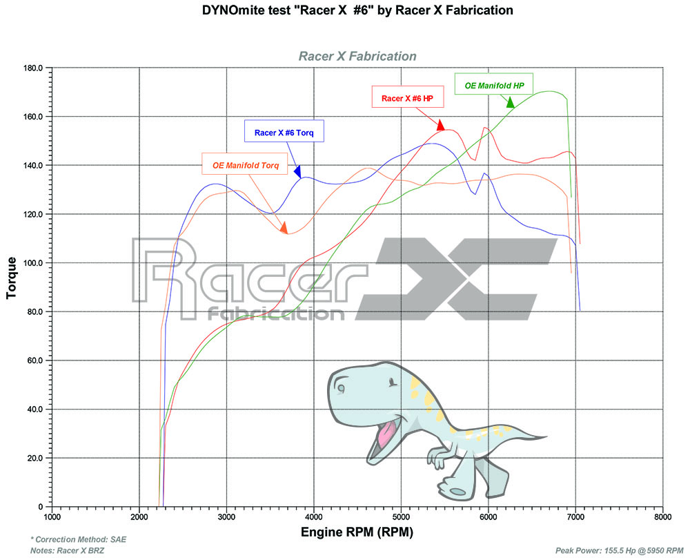
For manifold #6 we decided to test an outlier that would share a plenum size that was similar to OEM. The OEM manifold uses quite a small plenum, we estimate the volume around 80 to 100 cubic inches. The plenum we designed would be smaller than that, at 50% of our original plenum size. The results were very interesting. Enough so that we plan to test 1 more that is larger with a few extra tricks. The gains from the small plenum in the lower RPM range are very impressive with gains of up to 20 whp in the torque dip, however it lacks the plenum volume and runner size necessary to provide the power that is needed at the upper RPM range.
 Click graph to enlarge.
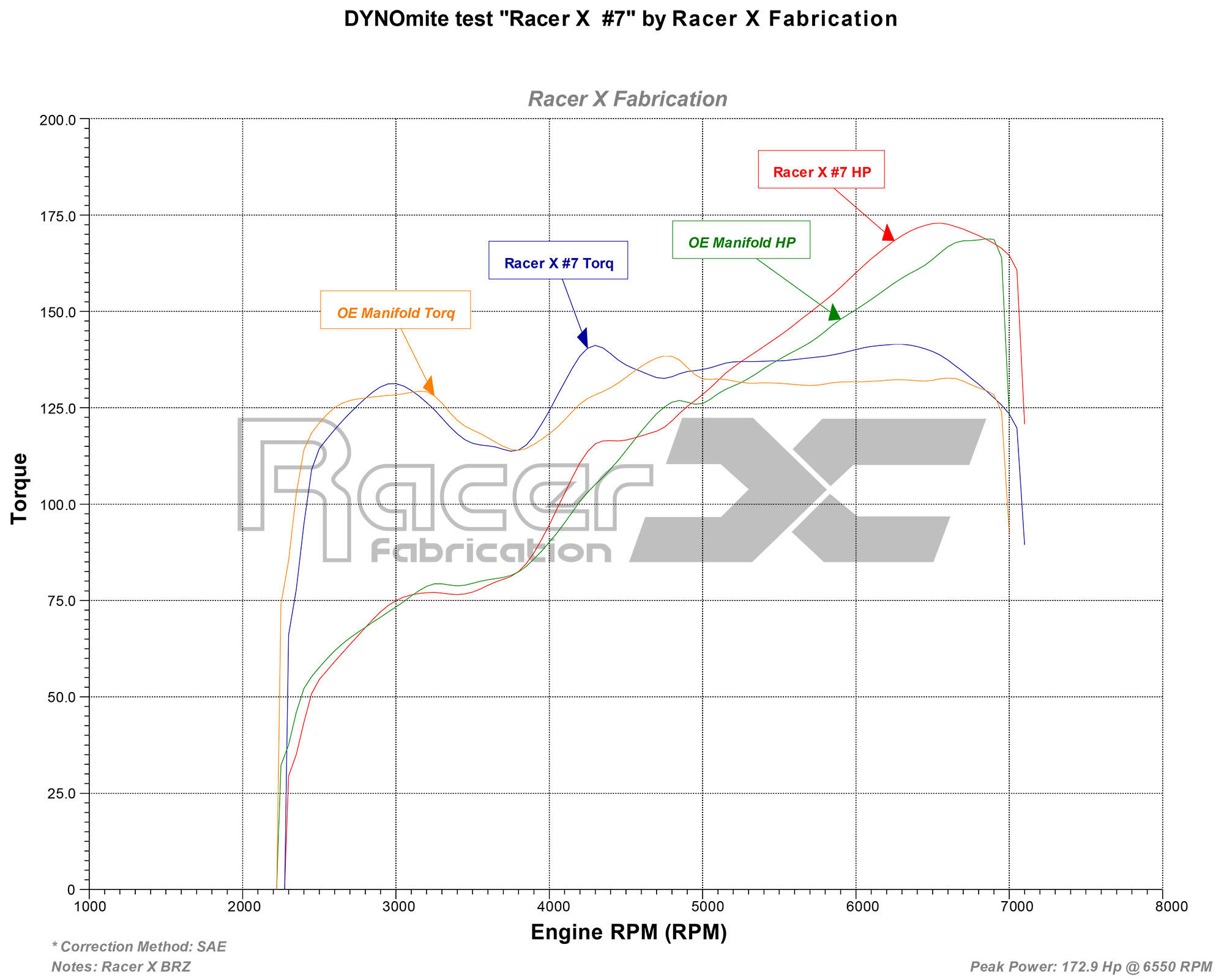
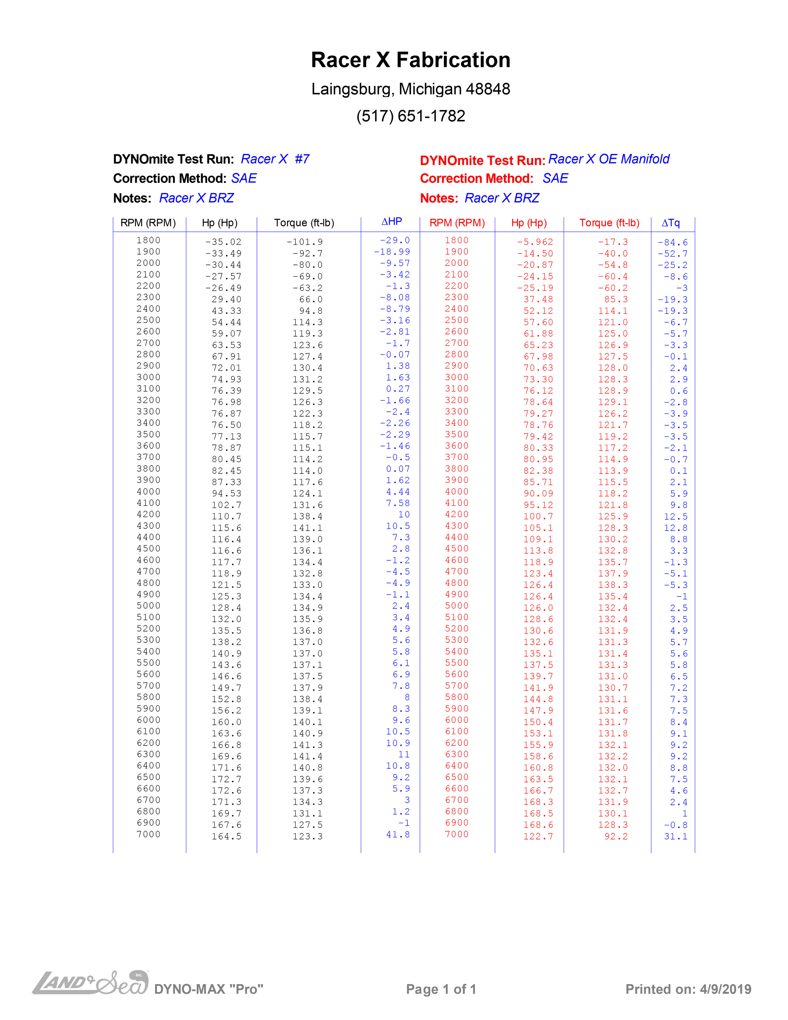
Well, after 6 failed attempts, why not try again? So here it goes… With manifold number 7, we took a deep dive and looked at all of our previous data. We saw a few elements that made power or had the potential to assist in making power, so we used those elements to design manifold number 7. Most of you probably overlooked the facet that manifold number 6 had pretty good improvements in the 3500 to 4000 RPM range when compared to OEM, and without mention, failed miserably at the higher RPM range. With manifold number 5, we modified our flange design and kept the larger runner diameter where it made the best power, but still less than OEM. We combined these manifolds and made a few tweaks to build manifold number 7. We kept the small plenum design and increased the runner diameter, yet again. These changes led to basically matching OEM power (well slightly higher than OEM), but peaks at 6550 instead of 6800. What it does do is increase horsepower and torque from 3900 to redline. There is a little hiccup from 4600 to 4900, but I have a feeling that actual tuning for the manifold could fix this.
 Click graph to enlarge.
We are now taking pre-orders, check out the product details here.
Looking forward to comments and questions, we will be updating again after we add a full exhaust system.
If you would like to receive updates on the development, please sign up below.